

Configuring Exit Nodes for Internet Traffic
Updated
Exit nodes route all internet-bound traffic from your devices through a designated routing peer. This guide explains how to configure default routes for internet traffic.
This feature requires NetBird version 0.27.0 or later.
Concepts
Default Routes
A default route (0.0.0.0/0 for IPv4) directs all internet traffic through a designated routing peer.
When IPv6 overlay addressing is enabled for the peer, the management server automatically creates a matching ::/0 route so that both IPv4 and IPv6 internet traffic flow through the exit node. Peers without IPv6 enabled have their IPv6 traffic blocked to prevent leakage.
Routing Peer
The routing peer acts as the exit node for internet traffic. It applies masquerading so that traffic appears to originate from the routing peer's public IP address.
An exit node route (0.0.0.0/0) matches all traffic, not just internet-bound traffic. Peers using the exit node can reach any network the routing peer can reach, including its local LAN.
You can limit this in two ways:
- Enable Block LAN access on the routing peer (in the peer's settings, or with
netbird up --block-lan-access) to block forwarded traffic to its local networks. It breaks site-to-site or LAN routes served by the same peer, so enable it only on a dedicated exit node. It does not restrict remote networks reachable through the exit node's upstream gateway. - Place the exit node on an isolated network segment (a DMZ or dedicated VLAN) that can only reach the internet. This enforces the restriction outside the peer and also covers upstream networks.
Both options assume the exit node does nothing else. If peers also need to reach resources on that site's LAN, serve those through a separate routing peer using a Network with scoped access policies instead of the exit node's broad route. For the full setup combining both, see Selective Internal Access Behind an Exit Node below.
For the mental model — see How Routing Peers Work — Exit node mode.
Distribution Groups
Peers in the distribution groups send their internet traffic through the routing peer once it connects.
The minimum access policy required for peers to use an exit node is Users (source) → Routing Peer (destination) over ICMP. Ensure a policy with this configuration exists for the distribution groups assigned to the exit node route.
Exit Node Selection and Auto Apply
Auto Apply answers one question: when a device receives an exit node, does it start using it immediately, or does it wait for the user to turn it on?
- Auto Apply enabled (the default): devices in the distribution groups start routing internet traffic through the exit node as soon as they receive it. Users do not have to do anything, and most will not notice.
- Auto Apply disabled: the exit node appears as an option in the user's NetBird menu, like an offered network they have not joined. Nothing changes until the user selects it there.
In both cases the user's own choice wins. A user who deselects the exit node on their device stays off it even with Auto Apply enabled, and a user who selects it manually stays on it. Auto Apply sets the starting position of the switch on each device; it is not a lock. It cannot enforce the exit node against a user's explicit choice. If your setup requires enforcement, see Enforcing the Exit Node on Managed Devices below.
Auto Apply requires NetBird client version 0.55.0 or later.
Existing Exit Node Routes
Exit node routes created before the Auto Apply feature was introduced are treated as having Auto Apply enabled. This preserves the previous behavior where exit nodes were applied automatically.
Clients running v0.55.0 or later auto-apply these routes unless the user has explicitly selected or deselected an exit node. Administrators can change the Auto Apply setting at any time.
Configuration Steps
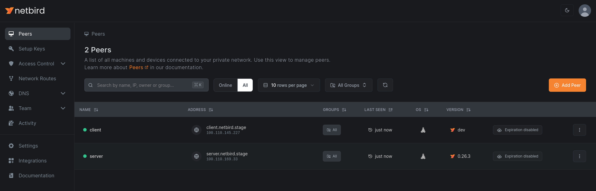
1. Open the Servers list
Navigate to the NetBird dashboard and open Peers (exit nodes are typically unattended machines like a VPS, router, or always-on host).
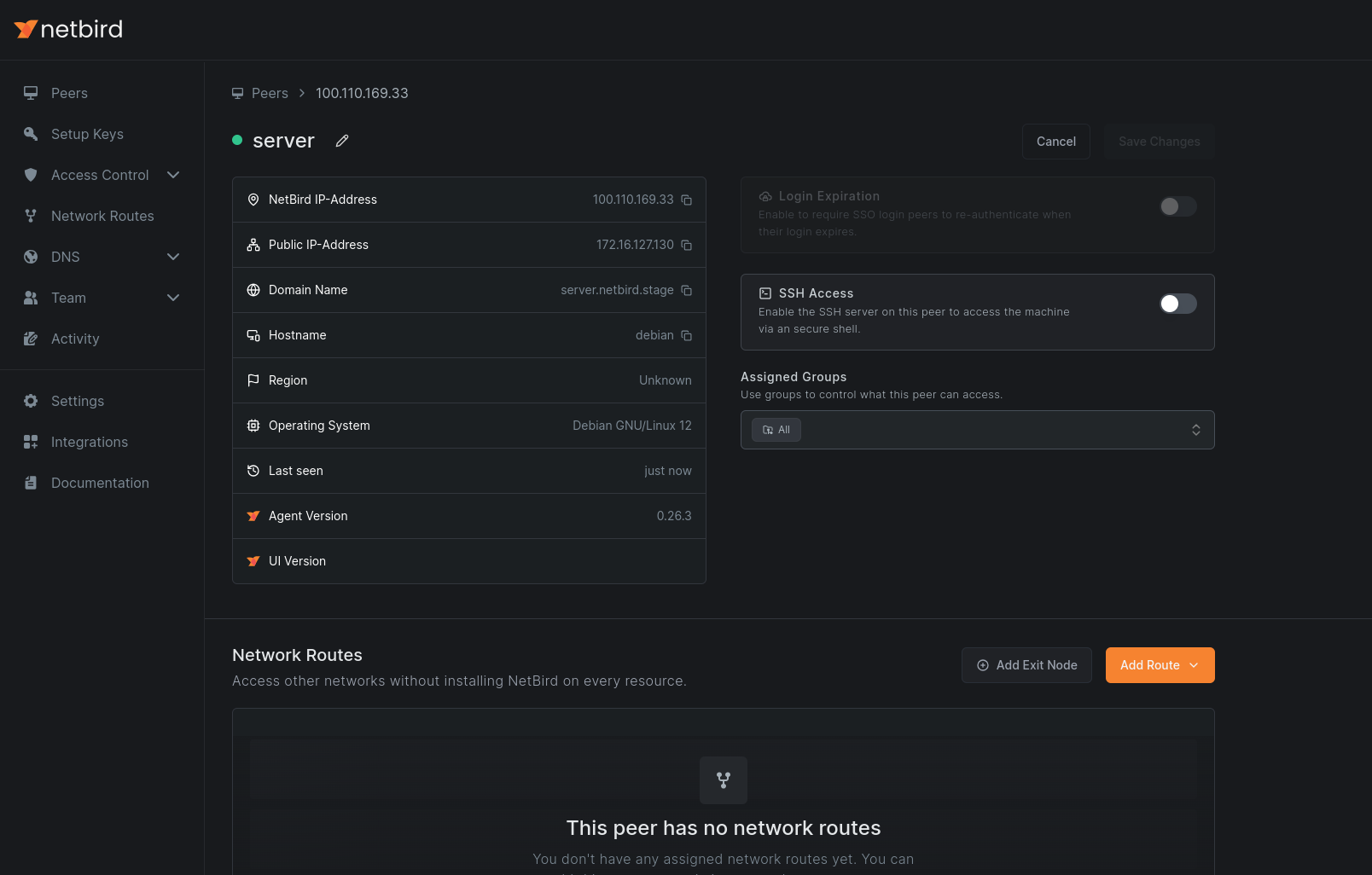
2. Select the Routing Peer
Choose the peer that will serve as your exit node.
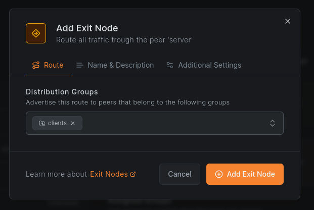
3. Configure the Exit Node
Click Add Exit Node. In the dialog, assign one or more distribution groups to specify which peers should use this exit node.
To make the exit node available without automatic activation, disable Auto Apply. Users can then enable it manually.
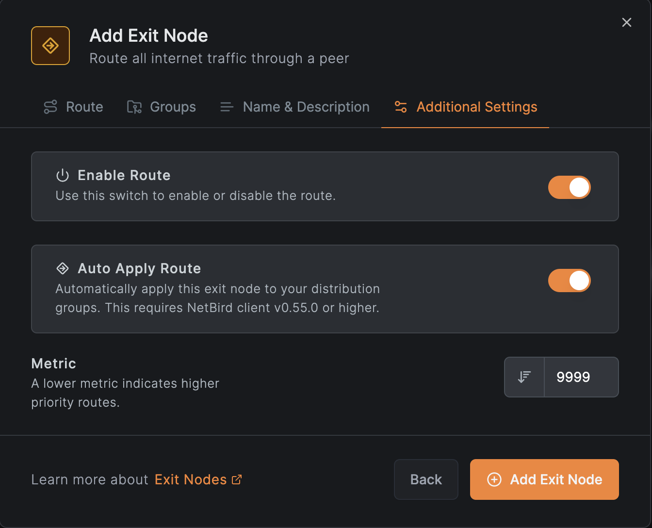
Click Add Exit Node to complete the configuration. Masquerading is enabled by default.
4. Verify the Configuration
Check the peer view to confirm the routing peer is marked as an exit node.
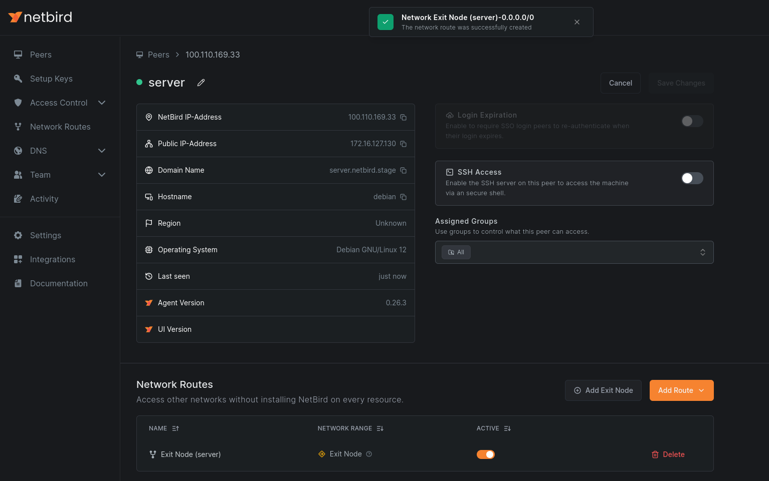
5. Configure DNS
Add a DNS server with the match domain set to ALL. Local DNS servers may not be accessible from the routing peer, and this also prevents DNS-based location leaks.
See Manage DNS in your network for details.
Regional Exit Nodes
A single exit node forces every user through one location: a user in Florida whose only exit node sits in California sends all internet traffic across the country and back. If your users are spread across regions, you want each device to exit near itself.
You get this by adding one routing peer per region to the same exit node with the same metric. When metrics are equal, each device measures its latency to every exit node and picks the lowest one, which in practice means the nearest one. With different metrics, you get primary/failover instead, so keep them equal for regional distribution.
The running example: an exit node in us-east and one in us-west, users on both coasts.
1. Deploy a routing peer per region
Set up one routing peer in each region as described in the configuration steps above. Both need masquerading and a stable internet path.
2. Add both peers to the same exit node
In the exit node's configuration, add both routing peers and leave the metric identical on both.
Adding the regions as two separate exit nodes does not work, and fails in a way that is easy to miss. Metrics and nearest-peer selection only apply between routing peers of the same exit node. Separate exit nodes instead appear on each device as independent choices in its exit node selector, and with Auto Apply enabled (the default) the client activates exactly one: whichever exit node's name sorts first alphabetically. Metrics and latency play no part in that choice. If the activated exit node's routing peer goes offline, the device keeps it selected and loses internet access entirely, even while another exit node's routing peer is online and connected. One exit node with multiple routing peers gives you selection and failover; separate exit nodes give you neither.
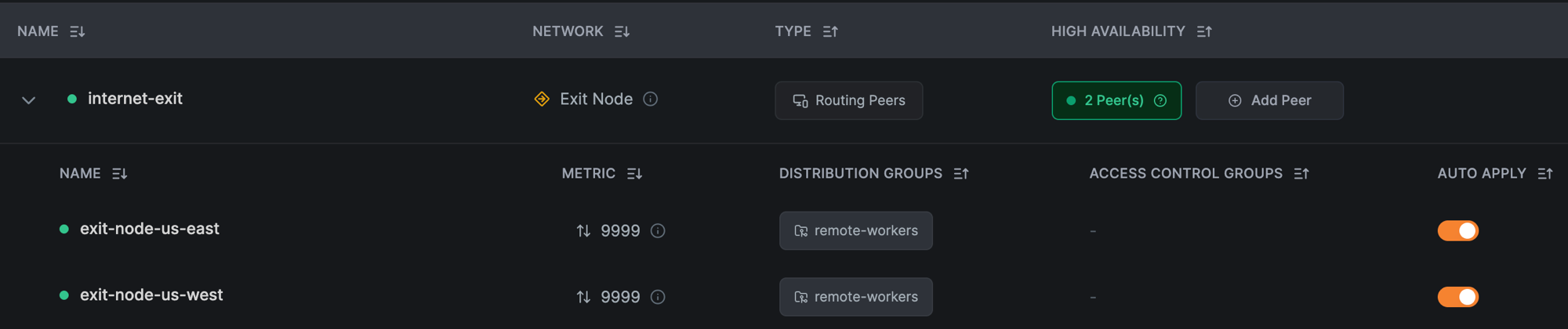
The finished state: one exit node, both regional routing peers under it with the same metric, and the distribution group on each.
3. Keep the distribution group and access policy scoped
Use a dedicated distribution group for the devices that should full-tunnel rather than the built-in All group, and keep the access policy one-directional from that group to the routing peers. Every device in the distribution group sends all of its internet traffic through whichever exit node it selects.
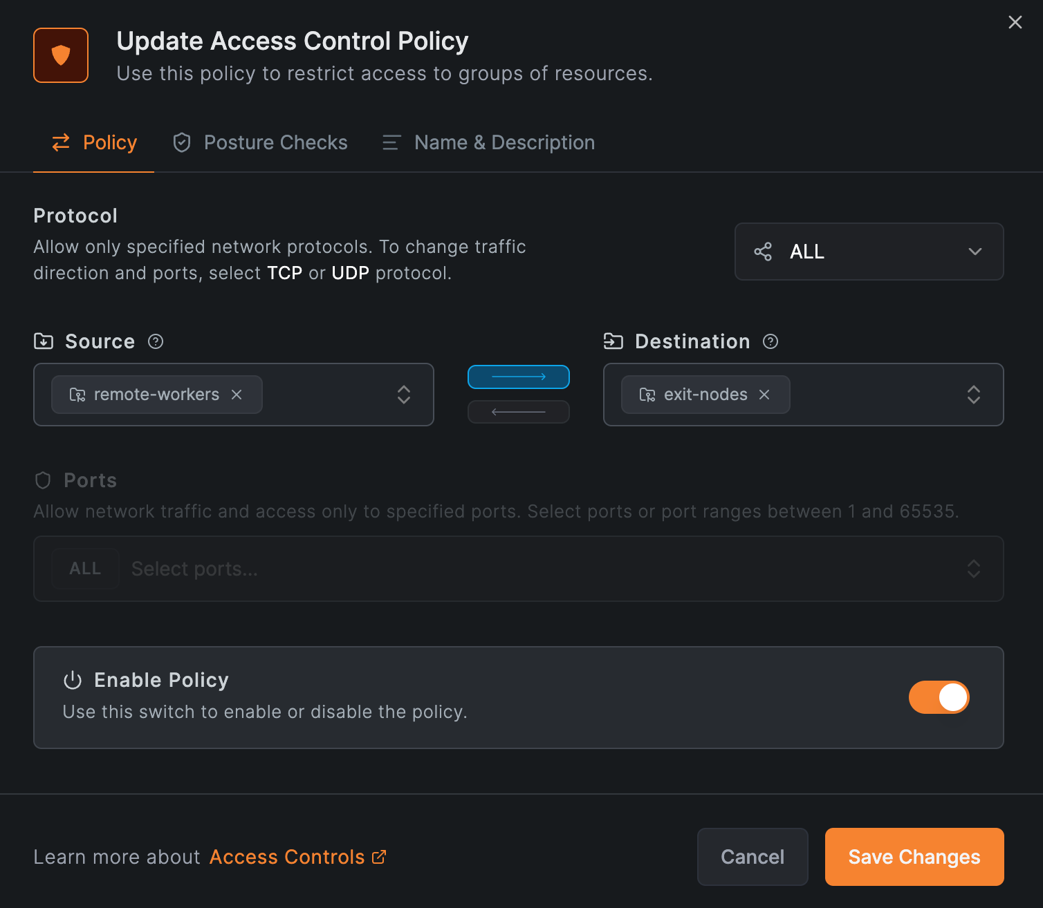
The policy that makes the exit nodes reachable: the distribution group as the source, the routing peers' group as the destination, one direction only.
4. Verify
On an east-coast device, run netbird status -d: the peer carrying the 0.0.0.0/0 route is the selected exit node, shown on its Networks line. Then confirm the egress path by checking the device's public IP against the us-east exit node's public IP. A west-coast device should show the us-west peer instead.
What this does and does not do
This is nearest-exit selection plus automatic failover, not load balancing: each device follows its own lowest-latency exit node, and traffic is not spread evenly across the exit nodes. See Nearest routing peer for the selection mechanism.
Latency-based selection is also not a guarantee of which exit node a given user lands on. If a rule must always hold, such as certain users always exiting in a specific country, use separate exit nodes with per-group distribution, or posture checks as in Geo-Based Exit Node Routing below. Make sure each device receives at most one exit node with Auto Apply enabled: enable it on one exit node per distribution group, and keep those groups from overlapping — more than one auto-applied exit node on a device is the failure mode described in step 2 above. Offer any additional exit nodes with Auto Apply disabled; users can switch between exit nodes manually in the client either way.
Traffic to your own sites is unaffected by any of this: routes to specific internal ranges are more specific than 0.0.0.0/0, so devices reach those resources directly through the routing peer that advertises them, regardless of which exit node carries their internet traffic.
Geo-Based Exit Node Routing
Some compliance setups require a device's location to decide its tunnel mode. A common example: company devices must send all internet traffic through a corporate exit node while traveling abroad, but keep a normal split tunnel at home, where only internal resources go through NetBird.
You can build this with a Country and Region posture check attached to the access policy that connects your users' group to the exit node's group. NetBird distributes a route only from a routing peer the device is allowed to connect to. When the posture check fails, the policy stops applying, the exit node peer drops out of the device's peer list, and the default route is withdrawn with it.
Devices that pass the check receive the default route and switch to a full tunnel. Devices that fail it do not receive the route, or lose it, and keep their split tunnel, with direct internet access and all other NetBird resources working as before. When the check changes, connected devices converge to the new state within about a minute, without reconnecting. A device is also re-evaluated each time it reconnects.
Attach the posture check to the policy between the users and the exit node peer, not to the exit node route's Access Control Groups. A check in that position only blocks traffic at the exit node: the default route still installs on every device in the distribution groups, and a device failing the check loses internet entirely.
The following example builds this goal: any device outside the United States sends all its internet traffic through the exit node, while devices inside the US keep their split tunnel. Traveling employees' devices are in the group remote-workers, and the exit node peer is in the group exit-nodes.
1. Create the Posture Check
Navigate to Access Control → Posture Checks, click Add Posture Check, and select Country and Region. On the Block tab, add United States, then save the check as "Outside the US".
Peers located in a blocked country fail the check, so the policy below stops applying to them and they keep their split tunnel. Peers anywhere else pass the check and get the full tunnel. NetBird determines the location from the public IP the peer uses to reach the management service, resolved with MaxMind's GeoLite2 City database, and shows it as country and city on the peer in the dashboard. On self-hosted deployments, the management server needs the database configured; see Geolocation Database.
2. Configure the Exit Node
Add the exit node as described in the configuration steps above, with remote-workers as the distribution group and Auto Apply enabled, so the full tunnel activates on its own whenever the route arrives. Leave the route's Access Control Groups empty; the policy in the next step does the gating.
3. Create the Access Policy
Navigate to Access Control → Policies and add a policy from remote-workers to exit-nodes, protocol ALL. Before saving, open Posture Checks, browse for "Outside the US", and attach it.
This must be the only policy that connects remote-workers to the exit node peer. If another policy also allows that connection, for example a broad All to All rule, the peer stays reachable through it, the route keeps arriving, and the posture check has no effect on the tunnel mode. Scope any other policies so they do not cover the exit node peer.
Also set a DNS server with match domain ALL; see Configure DNS above. Without it, devices keep sending DNS queries to their local resolver outside the tunnel, so a full-tunnel device still reveals its location through DNS even though all other traffic is tunneled. The nameserver applies to the whole group, and both tunnel modes handle it correctly: full-tunnel devices reach it through the exit node, while split-tunnel devices reach the same nameserver over their normal direct path. Resolution keeps working on both.
4. Verify
On a device outside the US, run netbird networks ls and confirm the exit node is listed and selected. Then check the device's public IP (for example with curl ifconfig.me): it should be the exit node's IP.
On a device inside the US, the same checks show no exit node entry, the device's own public IP, and working internet. netbird status no longer lists the exit node peer. Internal NetBird resources remain reachable on both devices.
Switching the Exit Node Off Inside the Office
The same shape solves a different everyday need: keep NetBird connected while a laptop is in the office, but send internet traffic through the office gateway instead of the exit node, and switch the exit node back on when the laptop leaves. Replace the Country and Region check with a Peer Network Range check with the Block action and your office subnet, for example 192.168.1.0/24, and attach it to the same policy. While the laptop's own address is inside that range, the exit node is withdrawn and the operating system uses its local gateway. When the laptop connects from anywhere else, the route returns and Auto Apply activates the exit node again.
The check compares the device's local interface addresses, as reported when the client connects, and the public IP it connects from. A local interface counts as its whole subnet, so the range you enter must be at least as wide as the netmask the office hands out: 192.168.1.0/24 matches a device on that /24, while a /32 or a /25 never will. See Peer Network Range for the matching rules. Windows and macOS clients reconnect on their own when the network changes, so the check is re-evaluated within seconds of the laptop moving. Linux clients do not, and are re-evaluated on their next netbird up or service restart. Android clients cannot report local ranges; see Peer Network Range Check on Android.
Enforcing the Exit Node on Managed Devices
Auto Apply turns the exit node on for every device in the distribution groups, but as noted above, it is not a lock: a user can still turn the exit node off in the NetBird menu or with netbird networks deselect. Compliance setups often need more than a default. Company devices must send their internet traffic through the exit node, and users must not be able to opt out.
You get this by combining Auto Apply with the disableNetworks client policy. The policy is enforced by the NetBird daemon on the device, which rejects every network selection call, so there is no way to change the selection from the client UI or CLI. Continuing the example from the previous sections: company laptops are in the group remote-workers, and the exit node peer is in the group exit-nodes.
The disableNetworks MDM key requires NetBird client v0.73.0 or later; the --disable-networks service flag requires v0.69.0 or later.
1. Configure the exit node with Auto Apply enabled
Set up the exit node as described in the configuration steps, with remote-workers as the distribution group and Auto Apply left enabled. Keep the distribution group dedicated to the devices that should full-tunnel, and keep the access policy one-directional from remote-workers to exit-nodes.
2. Lock network selection on the devices
Deliver disableNetworks: true to the devices through your device management tooling: a registry policy or Intune profile on Windows, a configuration profile on macOS. See MDM Integration for how the client applies a policy, and the Windows, macOS, and iOS pages for the payload formats and delivery options. The daemon re-reads the policy about once a minute, so it takes effect without restarting NetBird.
On Linux devices and servers, where there is no MDM channel, set the equivalent flag when installing the service:
netbird service install --disable-networks
With the policy in place, the Networks and Exit Node menus disappear from the client UI, and selection commands are rejected by the daemon:
netbird networks deselect all
# Error: failed to deselect networks: network selection is disabled by the administrator
A common mistake is reaching for disableUpdateSettings instead: that key makes the device's NetBird configuration read-only, but it does not touch network selection. disableNetworks is the key that locks the exit node.
3. Deploy the lock before users touch the switch
Order matters. A user's exit node choice is saved on the device, and a deselection made before the policy arrives keeps winning over Auto Apply afterward: the policy blocks new selection calls, but it does not clear a choice that was already saved. Roll out disableNetworks before (or together with) the exit node, not after users have discovered the toggle.
If a device is already stuck in that state, clear its saved selection once: stop the NetBird service, delete the daemon state file (/var/lib/netbird/state.json on Linux; the same file in the NetBird data directory on other platforms), and start the service again. The exit node auto-applies on reconnect.
4. Verify
On a locked device, netbird networks list returns the "network selection is disabled by the administrator" error instead of a network list, and the device's public IP (for example with curl ifconfig.me) matches the exit node's public IP. To confirm the policy reached the daemon at all, use netbird debug config as described in Verifying enforcement.
What this does and does not do
With Auto Apply and disableNetworks in place, every device in remote-workers routes its internet traffic through the exit node, and no user can select, deselect, or switch exit nodes from the device. Enforcement lives in the daemon, so the CLI and the UI are equally locked.
It does not make the tunnel itself mandatory. A user can still disconnect NetBird entirely with netbird down, and a user with administrator rights on the device can stop or remove the service; NetBird has no always-on or kill-switch mode. Enforce that layer with the operating system: run devices with standard user accounts, manage the NetBird service through your MDM, and design your access policies so that disconnecting from NetBird costs the user access to company resources instead of freeing them from restrictions. The disableUpdateSettings and disableProfiles keys close the remaining side doors of reconfiguring the client or switching to an unmanaged profile; see Lock the client app.
Selective Internal Access Behind an Exit Node
An exit node grants more than internet access. Its 0.0.0.0/0 route matches all traffic, so devices using it can reach any network the exit node's host can route to, including internal networks you never exposed as a resource. If your users need specific internal resources plus a full tunnel, but must not reach everything the site's routers can see, the exit node's route cannot express that on its own.
The fix is an architecture, not a setting: split the roles across two routing peers. Serve the internal resources from a routing peer inside the data center, where specific routes and access policies decide exactly what is reachable. Run the exit node on a host that can reach only the internet, so its unbounded route has nothing internal to expose.
The running example: devices in the group remote-workers must reach 10.60.0.0/20 and the single host 10.70.5.20, must not reach 10.90.0.0/20, and send all internet traffic through the company exit node. The data center's routers can reach all three networks.
1. Serve the internal resources from a routing peer inside the data center
Create a Network (for example datacenter) with a routing peer that sits inside the data center. Add exactly the resources users need: one for 10.60.0.0/20, and one for the single host 10.70.5.20. Grant access with a one-directional policy from remote-workers to those resources.
Create no resource for 10.90.0.0/20. NetBird denies by default: a subnet you never add as a resource gets no route and no accept rule, so this peer cannot take users there.
2. Deploy the exit node where it cannot reach the internal networks
Run the exit node on its own host, and place that host in a network segment with internet-only egress: a DMZ subnet, a dedicated VLAN, or cloud egress rules that keep private ranges unreachable. Configure the exit node as described in the configuration steps, with remote-workers as the distribution group.
This placement is the actual enforcement. Traffic to 10.90.0.0/20 still matches the default route and arrives at the exit node, but the host has no path to the destination, and nothing configured in NetBird can reopen it.
Two shortcuts do not achieve this, and both are worth naming:
- Block LAN access alone is not enough. As noted above, it blocks only the networks on the exit node's own interfaces. A network one gateway hop away, like
10.90.0.0/20behind the data center router, is still forwarded. - Host firewall rules on the exit node are not a reliable substitute. To keep routing working alongside firewalls such as ufw or firewalld, NetBird inserts allow rules for its own interface at the top of forward chains on the host, including chains created after it starts. Filtering added there does not take effect for tunneled traffic. Restrict the host at the network layer instead: an upstream ACL, the VLAN, or the cloud egress rules.
The two allowed resources are unaffected by any of this: their routes are more specific than 0.0.0.0/0, so devices reach them through the data center routing peer no matter which exit node carries their internet traffic.
3. Enable Block LAN access on the exit node
With the segment doing the real work, enable Block LAN access in the exit node peer's settings as an additional guard for the one network the segment cannot remove: the exit node's own subnet. Since this exit node serves no LAN resources, the setting costs nothing here.
When setting it from the CLI on a peer that is already connected, disconnect first. netbird up --block-lan-access on a connected peer reports Already connected and does not apply the flag:
netbird down
netbird up --block-lan-access
4. Verify
The design rests on one property, so test that property directly on the exit node's host: try to reach an address inside 10.90.0.0/20, for example with curl --max-time 5 10.90.0.10 or a ping. If the host can reach it, tunneled devices can too, and the segment's egress restriction needs fixing before anything else matters.
Then confirm the user-visible behavior from a device in remote-workers:
- The allowed resources respond: a host in
10.60.0.0/20and the host10.70.5.20are reachable. - The forbidden network does not respond: connections to addresses in
10.90.0.0/20fail. Depending on how the segment enforces egress, they time out, are rejected, or report an unreachable route; any of these is the correct result. - Internet traffic exits through the exit node: the device's public IP (for example with
curl ifconfig.me) matches the exit node's public IP.
What this does and does not do
Users get precisely the two internal resources and a full tunnel, and the forbidden network stays unreachable even though every packet toward it still arrives at the exit node. That restriction is enforced by where the exit node lives, so no dashboard change, policy mistake, or client setting can expose the forbidden network through it.
It does not restrict what the data center routing peer exposes: that peer's host can reach 10.90.0.0/20, and only its resource list and policies keep users out. Keep those scoped to exact prefixes and single hosts, and treat any new resource on that peer as a deliberate access decision.
Performance Expectations
An exit node carries each device's entire internet traffic through a single WireGuard tunnel, and a single tunnel is processed largely on one CPU core of the exit node. This caps each device's throughput at single-tunnel speed: typically a few Gbps on a modern server CPU running Linux kernel WireGuard. The exact figure depends on the exit node's per-core speed, the tunnel MTU, and traffic direction (see the benchmark assumptions), but it does not grow with parallel streams.
Because this is a fixed cap rather than a percentage cost, what you observe depends on your internet line rate:
- On links up to about 1 Gbps, an exit node typically adds little to no throughput loss.
- On multi-gigabit links, full-tunnel throughput tops out at the tunnel cap, so a large relative drop against a 5 or 10 Gbps line is expected behavior, not a misconfiguration.
A common mistake is scaling the wrong dimension: adding CPU cores to the exit node or running more parallel streams on a device does not raise that device's ceiling, because the tunnel still serializes on one core. Per-core CPU speed does raise it, so for fast individual clients pick the exit node hardware with the fastest single-core performance available. More cores raise the aggregate capacity across many devices; see Sizing Routing Peers for measured per-size numbers.
If throughput lands well below a few Gbps, check these before resizing hardware:
- Relayed connection. Run
netbird status -don the device and confirm the connection to the exit node shows type P2P. Relayed traffic is significantly slower than a direct connection. - Userspace WireGuard. Devices on Windows and macOS, and peers running in userspace mode, reach well below kernel-mode numbers.
- Exit node limits. If the connection is P2P and both ends run kernel WireGuard, check the exit node's CPU load, the tunnel MTU, and the traffic direction against Tuning for more throughput.
IPv6 Support
IPv6 overlay addressing requires NetBird v0.71.0 or later on both the routing peer and the clients.
When IPv6 is enabled in your account settings and the exit node peer supports it, the management server automatically generates a ::/0 route alongside the 0.0.0.0/0 route. No additional configuration is needed.
For peers that do not have IPv6 enabled (older clients, or accounts with IPv6 disabled), IPv6 traffic is blocked at the tunnel interface to prevent unintentional leakage through the exit node.
You can disable IPv6 on individual clients with the --disable-ipv6 flag:
netbird up --disable-ipv6
See IPv6 Overlay Addressing for more details on enabling IPv6 for your account.
High Availability
Exit nodes support high availability configurations. With equal metrics you get nearest-exit selection as described in Regional Exit Nodes; with different metrics you get primary/failover. See Creating Highly Available Routes for more information.